

A mounting bolt can appear fully seated while its tip contacts debris at the bottom of a tapped hole, leaving the bracket barely compressed. Another joint can have ample nominal thread depth yet strip its weak internal threads. I evaluate bolts through usable engagement, mating material, bearing support, and the measured assembly response. This article establishes what must be verified before thread length becomes an engineering requirement.
I follow the axial force from the head through the bolt body and into the mating thread flanks. Tightening advances the helical interface until the head and members seat, then additional movement establishes elastic stretch. The mating material reacts that tension through the engaged threads. The resulting compression exists only if the correct surfaces are in contact and the rotation is not being stopped by an unintended obstruction.
Thread engagement is therefore a geometric and mechanical quantity. Nominal tapped depth can include an entry chamfer, incomplete threads near the bottom, and regions that the installed bolt does not reach. Bolt length can include a tip form that contributes little usable flank contact. I assess the overlap of complete, correctly formed threads in the assembled condition rather than measuring the hole and screw independently and assuming their lengths add up to capacity.
Load is not automatically shared equally by all engaged turns. The elasticity of the bolt, Nut or tapped member, and thread geometry affects the distribution. A damaged entry region may shift load into the remaining contact. Material yielding can redistribute some demand, but this is not a reason to accept missing or distorted threads without analysis. The actual mating material and finished condition must be part of the capacity comparison.
The joint can fail through bolt rupture, external-thread damage, internal-thread stripPing, or failure of the surrounding member. Its head seat can also deform before any thread limit is reached. I examine these competing mechanisms because a longer engagement may improve one boundary while leaving another unchanged. Adding screw length can even remove bottom clearance and create false seating.
The supplied technical-standards field and verified specification appendix are empty. No standard, certificate, engagement ratio, torque value, or acceptable thread capacity is asserted. Verify the required geometry and mechanical limits against the manufacturer's current test reports and the approved drawing before using them in a specification.
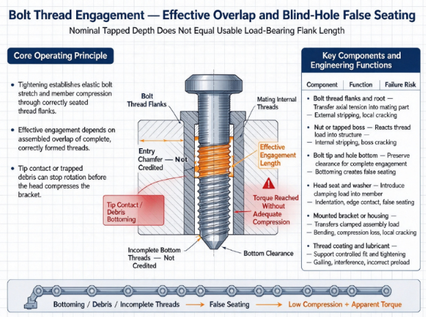
I separate dimensions that establish fit from properties that establish capacity. A thread gauge can identify a geometric condition, but it does not measure the strength of a casting or confirm that the bracket has been compressed. Each part needs evidence appropriate to its function in the assembled force path.
| Component | Material Spec | Function | Failure Risk if Compromised |
|---|---|---|---|
| Bolt thread flanks and root | Verify finished material properties, tolerance, surface integrity, and complete thread geometry. | Transfers axial tension into the mating part. | External stripping, local cracking, or unstable contact. |
| Nut or tapped boss | Verify actual material condition, usable thread depth, and surrounding section. | Reacts thread load and distributes it into the structure. | Internal stripping or cracking of the surrounding boss. |
| Bolt tip and hole bottom | Verify tip form, drilled depth, incomplete-thread region, and cleanliness. | Preserves clearance while complete threads engage. | Bottoming creates torque without adequate compression. |
| Head seat and washer | Verify hardness, flatness, contact area, and radius clearance. | Introduces clamping load into the member. | Indentation, edge contact, or false seating. |
| Mounted bracket or housing | Verify thickness, stiffness, hole position, and local bearing support. | Transfers the clamped assembly load. | Bending, compression loss, or local cracking. |
| Thread coating and lubricant | Verify thickness effects, friction response, and application process. | Supports controlled fit and tightening behavior. | Galling, interference, or incorrect preload. |
Verify all parameters against current test reports and applicable standards before use in specifications.
When a thread is repaired, I identify the complete repair system and the surrounding geometry rather than treating the original designation as unchanged. Insert retention, available wall section, parent material condition, and finished alignment can alter the load path. The repair must provide evidence for the intended assembly and any approved service cycles.
I also identify which member rotates during tightening. A rotating bolt head and a rotating nut produce different bearing contacts. A flange or captive element can conceal partial seating if its geometry is not compatible with the mating surface. These details belong in the drawing and assembly record.
The required engagement must be established from capacity and geometry, not chosen from a universal length-to-diameter rule. I compare the actual limiting mechanisms using verified finished properties, then validate the uncertain boundary with representative components. A destructive test is useful only if the specimen reproduces the intended materials, usable engagement, support, and assembly condition.
| Parameter | Standard | Test Method | Acceptable Range | Implication if Out of Range |
|---|---|---|---|---|
| Complete effective engagement | Not supplied; verify the approved method. | Inspect assembled overlap after excluding chamfers, incomplete threads, and runout. | Verify against current drawings and capacity reports. | Available thread flank capacity is overstated. |
| Internal and external stripping capacity | Not supplied; verify the approved method. | Analyze verified materials and conduct representative axial failure testing where required. | Verify the approved capacity and uncertainty allowance. | Thread failure precedes the intended design boundary. |
| Bottom and shoulder clearance | Not supplied; verify the approved method. | Check assembled tolerance stack, tip position, and contact evidence. | Verify clearance across approved configurations. | False seating prevents the intended compression. |
| Bearing-face response | Not supplied; verify the approved method. | Inspect contact imprint and permanent indentation after assembly loading. | Verify against drawing and finished-material evidence. | Clamp force decays through local deformation. |
| Torque, rotation, and preload | Not supplied; verify the approved method. | Record the tightening trace with independent clamp-force measurement. | Verify the actual finish and lubricant process window. | Friction or obstruction is mistaken for successful seating. |
Verify all parameters against current test reports and applicable standards before use in specifications.
Test fixture design must distinguish stripping from unsupported bending or local boss failure. I record the loading alignment, seating faces, specimen damage, and exact failure location. Results from specimens that fail outside the intended engagement mechanism need separate interpretation. A maximum force without a documented failure mode is insufficient to validate the calculation.
Adequate engagement protects a joint by providing a verified path for axial force through complete mating thread flanks. That path depends on the strength and deformability of both materials, their geometry, and the section surrounding the internal thread. The bolt's mechanical designation does not describe the entire interface. I assess whether the controlling boundary is internal stripping, external stripping, tensile rupture, or failure of the tapped boss before approving an engagement length.
I establish effective length from the assembled geometry. Entry chamfers remove usable flank area at the opening. A tap's incomplete region can leave the deepest part of a hole unsuitable for full load transfer. Bolt thread runout and its unthreaded shoulder can also reduce overlap or stop the assembly prematurely. I examine actual manufactured features and tolerance combinations instead of converting drawing depth into assumed complete engagement. Verification needs the worst approved combination, not only a conveniently fitting sample.
Blind-hole clearance provides a different protection. The tip must remain clear of the hole bottom and any region that is not intended to react assembly force. Chips, compacted debris, lubricant accumulation, or an excessively long bolt can stop advance before the head compresses the bracket. The resulting torque may look credible while the useful load path is absent. I correlate the torque-angle trace with independently measured compression and physical seating evidence. A high final reading cannot establish clearance.
This connects the engagement gap with the torque-to-preload gap. Coatings and lubricants change friction, and locking elements add rotational resistance. A joint that strips under a lubricated installation may have developed more tension than its dry qualification specimen at the same torque. Conversely, a rough or damaged mating thread can consume torque and leave low compression. I therefore qualify the actual mating pair, finished state, and application procedure together. The test must identify both the force attained and the mechanism that limits further loading.
Bearing support is coupled to thread strength. A thin washer or soft housing face can indent while the engaged threads remain intact. That indentation relaxes the elastic force couple, allowing separation or slip under service. Edge contact beneath the head or interference at a radius can concentrate pressure and create misleading apparent seating. I verify the full intended contact area and its load response. Increasing thread length cannot restore compression lost through an inadequately supported head seat.
Dynamic loading adds demands that a static engagement check does not establish. A moving bracket can impose bending on the bolt, concentrate demand at the first effective threads, or repeatedly open the interface. Thread fretting and damage can then evolve even if the monotonic stripping capacity was acceptable. I identify load direction, grip length, and any shear plane through a threaded section, then monitor residual preload and movement during representative cyclic or impact loading. Qualification must preserve the actual supporting geometry.
The mating material can also change with temperature and service history. A housing that has been repaired, overheated, corroded, or repeatedly assembled may not retain the condition used in its original calculation. I do not credit a stronger bolt with strengthening that housing. Capacity evaluation must use verified evidence for the installed material, including the surrounding boss and any insert or repair. Where that evidence is missing, the parameter remains unapproved until a representative test or current report resolves it.
Surface processing requires its own failure review. Coating thickness can affect fit, while friction influences the tension developed during assembly. Cleaning or electroplating can introduce hydrogen into susceptible finished material, which under sustained tensile stress can produce delayed fracture. I link hardness evidence, coating route, relief-treatment records where required, and approved sustained-load verification to the same lot. A thread-capacity test that ends immediately after reaching load does not answer every delayed-fracture question.
The final protection is a controlled acceptance method. Gauging, dimensional inspection, torque testing, and destructive loading answer different questions. I specify which evidence establishes complete engagement, which confirms actual compression, and which qualifies material capacity. Near an acceptance boundary, measurement uncertainty and test variability must be considered explicitly. This prevents a nominally correct thread label, a high torque reading, or a surviving isolated specimen from replacing the evidence needed for the complete assembled connection.
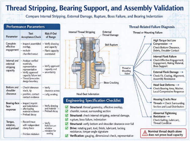
When I examine thread-related damage, I preserve the bolt, the mating member, and any debris before destructive sectioning. The distribution of displaced material and the location of first contact can distinguish false seating from overload. I also retain tool traces and assembled dimensions so that the mechanical interpretation can be checked against the process history.
Blind-hole bottoming occurs when the bolt tip or compacted material reacts the tightening force before the head fully seats. The consequence is low useful clamp force despite a high torque reading. Prevention requires clearance verification over the tolerance stack, controlled cleanliness, and a trace linked to measured compression.
Internal-thread stripping occurs when the usable mating flank area and material strength cannot carry the developed axial force. Entry chamfers, incomplete bottom threads, damaged flanks, or a weak boss can reduce the available boundary. Prevention requires effective-engagement inspection, verified material capacity, and representative axial failure testing where the analysis remains uncertain.
External-thread damage occurs when the bolt's flank or root region is the weaker part of the pair or has been damaged by interference. The consequence can include metal transfer, reduced engagement, or later fatigue initiation. Prevention requires fit verification in the finished condition and investigation of coating thickness, alignment, and assembly resistance.
Head-seat indentation occurs when bearing pressure concentrates on a soft or partially supported surface. The consequence is preload loss without nut rotation. Prevention requires compatible seat geometry and verified local compressive response, followed by retained-force measurement after representative loading.
Boss cracking occurs when the reaction from the engaged thread spreads into an inadequately supported surrounding section or combines with service bending. The consequence can be housing failure even though the thread flanks remain recognizable. Prevention requires evaluating the complete boss geometry and boundary conditions rather than treating the tapped hole as an isolated material block.
Galling occurs when local thread contact transfers material and creates increasing resistance or seizure. The consequence may be twisted fasteners, stripped flanks, or an incomplete clamp state. Prevention requires a validated material and lubrication combination, controlled tightening conditions, and rejection of traces indicating abnormal resistance.
I organize the specification around the complete connection and its permitted variants. Every listed limit must point to an approved drawing, current material report, or representative validation result. Nominal engagement and nominal torque remain descriptive fields until their relation to the limiting mechanisms is established.
Structural: define bolt and mating-thread geometry, finished tolerance, complete usable overlap, entry chamfer, runout, and minimum surrounding member section from verified evidence.
Structural: identify internal stripping, external-thread damage, bolt rupture, boss failure, and bearing indentation as separate capacity checks.
Structural: verify blind-hole bottom clearance and shoulder clearance across the full approved tolerance stack and installed member thicknesses.
Structural: establish retained compression and permitted service movement using the actual bracket, housing, washer, and thread support.
Drive specifications: control the rotating part, tool configuration, finish, lubricant, locking resistance, and torque-angle signature associated with validated preload.
Environmental: assess temperature, corrosion, contamination, cleaning, and prior assembly history for both fastener and mating member.
Safety standards: confirm any project-required standards through technical approval; no standard number or certificate is asserted here.
Verification: define gauging, dimensional inspection, representative failure testing, uncertainty treatment, and disposition for damaged or repaired threads.
For repaired threads, I require an identified repair drawing and evidence for the installed configuration. The acceptance record should state which original dimensions changed, how usable engagement was verified, and whether support or load sharing differs from the original assembly. Repeatedly installing longer bolts into a worn hole is not a controlled repair method.
Ningbo yi teng construction machinery CO,LTD is described in the supplied company information as producing standard and nonstandard fasteners for machinery applications. The bolts product page should separate nominal dimensions from validated mating-thread and bearing-support requirements.
I evaluate whether engineering personnel can analyze the complete mating pair, inspect usable thread geometry, and conduct representative failure testing with documented mechanisms. Finished-condition gauging and material reports need traceability to the tested components. A useful report identifies exactly which dimensions and material states were reproduced.
Capability also includes controlling coating effects on fit, documenting abnormal assembly traces, and retaining failed mating members rather than examining only the bolt. Where a customer uses a casting or repaired housing, the test boundary must identify that part clearly. No current certification is established by the supplied technical-standards field; verify any required certification before specification.
The required effective engagement must be established for the actual materials, geometry, and load path.
A universal engagement ratio cannot replace a comparison of stripping, rupture, and surrounding-member capacity. I exclude chamfers, incomplete threads, and runout from credited usable overlap. Verify the resulting requirement against current reports and the approved assembly analysis.
Yes, bottom contact can create rotational resistance before the joint is adequately compressed.
The tip, incomplete bottom threads, or trapped material can become the unintended reaction surface. I check clearance over the tolerance stack and correlate the tightening trace with independent clamp-force evidence. Final torque alone cannot prove correct seating.
No, a thread gauge establishes a geometric condition rather than the complete assembled capacity.
Mating material strength, usable engagement, and surrounding support remain separate questions. The finished coating condition must also be included. Representative capacity testing or verified analysis is needed when those boundaries are uncertain.
Only after the casting, engagement, and assembly preload have been reassessed.
A stronger fastener may develop a load that the original internal threads or bearing face cannot carry. I compare all competing failure mechanisms rather than approving the substitution from the bolt designation. Current material evidence for the actual casting is required.
Qualify the identified repair system in the representative member and load path.
Verify usable engagement, surrounding section, alignment, and insert retention where applicable. The repair test must include the intended assembly and service conditions. The original thread designation does not by itself establish the repaired capacity.
Share your project parameters for a technical review.
Pessoa de contato: Sra. Wu
Telefone:0086-13958324455
Atendimento ao cliente: +86-0574 88065928
E-mail: Sales@zjbzj.com
Fax: +0086-0574 88065656

site oficial
Copyright @ Ningbo yi teng Construction Machinery CO, LTD principalmente envolvida em séries de parafusos de lâmina, parafusos hexagonais e dentes de caçamba. Bem-vindo a perguntar!
Mapa do siteEste site usa cookies para garantir que você tenha a melhor experiência em nosso site.
 English
 Español
 Pусский
 Français
 Deutsch
 日本語
 한국어
 العربية
 हिन्दी



 Whatsapp
 Telefone
Comente
(0)